-
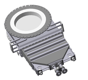
1. Hot blast valves are intended for separation of a hot-air stove from a hot blast main under "on-gas" operation of the former.
-
2. Hot blast valves can be used as a shutoff one for separation of a gas burner from the hot-air stove under "on-blast" operation of the latter.
-
3. Hot blast and shutoff valves are installed vertically in a pipeline. The pipeline is opened and closed by the movement of the valve disk with the use of electromechanical drive. In event of power failure, it is possible to operate the drive manually.
|
Valve specifications |
|
|---|---|
|
Working section dia, mm |
1100 |
|
Max hot-blast temperature, °C |
1400 |
|
Max hot-blast pressure, MPa |
0,5 |
|
Possible blast pressure differential when valve is opened (closed), MPa |
0,01 |
|
Disk travel, mm |
1550 |
|
Type of cooling |
water |
|
Max cooling system pressure, MPa |
0,55 |
|
Design cooling water discharge (inlet and outlet temperature differential Δt=10°C), m3/h valve housing valve disk Cooling water must be cleaned from mechanical impurities Max required suspended substances concentration, mg/l Required cooling water hardness, meg/l Max required temperature of outlet cooling water, °C |
18 10 30 1,5…2,5 40 |
|
Dimensions, mm length, L height, H width, A |
500 4170 2220 |
Design features
New design of the valve combines all modern features which have shown excellent results under service conditions both at Russian and foreign metallurgical plants.
All heat-loaded elements of the valve excluding disk contact surfaces and housing thrust rings are protected with refractory lining. Housing cooling system allows to effectively cool thrusting rings, the most heat-loaded elements of the valve, as well as attachment flanges and housing neck zone providing normal working conditions of flange packings.
The valve disk has a solid shell and spiral partitions which form disk cooling system.
Cooling water velocity both in the housing and in the disk is above 1 m/sec which ensures removal of mechanical suspensions and eliminates the danger of cooling ducts blockage.
Significant reduction of cooling water discharge and maximal protection of heat-loaded elements with refractory lining allow to decrease heat losses.
To increase lining durability modern reinforcing elements are used. Due to their design features the elements can keep refractory materials.
The "Graflex" made on the base of thermal expanded graphite is used in "housing-cover" flange packing and in stuffing-box seals of tubes supplying cooling water to the valve disk.
During manufacturing process valves undergo all basic tests including air and leak ones.
Supplier reserves the rights to change valve design in order to increase its technical and economic characteristics.
Standard schedule of supplies
Technical documentation
- valve assembly drawing
- certificate
- technical description and operating manual
Valve mechanical equipment is supplied according to 1-368912 drawing.
Supplier guarantees complete interchangeability of the above mentioned valves 1100 mm and similar valves delivered earlier by EZTM and other suppliers.

